A Quick and Dirty Buck converter
Using an Arduino Nano, a IGBT halfbridge module, and some parts I had laying around
Design
I decided to build this buck converter to learn about their theory of operation and to gain some better experience working with power electronics. I decided to use an arduino nano to build a simple Bang-Bang type controller. I have the Arduino direct control over a GDIC (Gate Drive IC) and feedback via a resistor divider.
Circuit and PCB Design
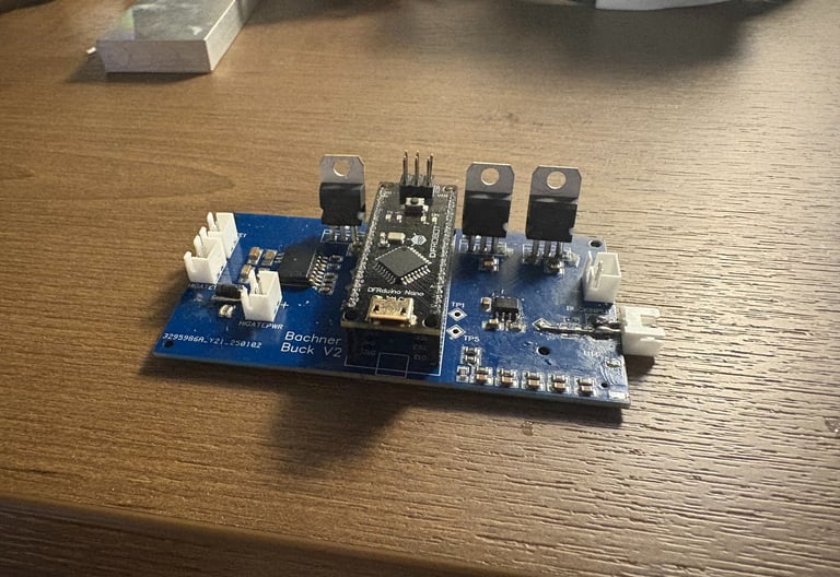
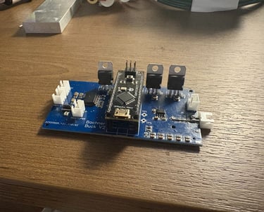
Unfortunately Ive lost the schematic and EDA files for this project, but I still have the physical board. Keeping it simple, from left to right, there is the gate driver, Arduino, then op-amp input and feedback input. The GDIC keeps the gate drive section fairly trivial, it just needs a few passive components to work and I gave it its own power supply regulator because I was worried that allowing it to share a power supply with the Arduino would lead to problems. A input from the bottom right connector feds into a low pass filter than op-amp (I decided to control this board via pwm, so first the low pass filter gives us a analog voltage then the op-amp creates a better input impedance) then into the Arduino. The Arduino compares the input to the feedback and controls the Buck based on the difference of the two.
The Power Electronics
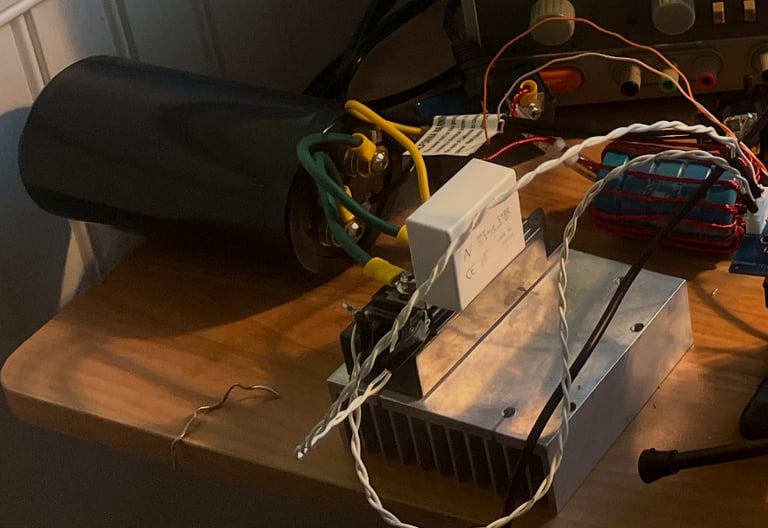
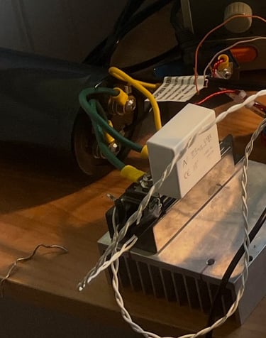
The power electronics were very simple, I found the control scheme to be much more complicated than the actual converter. First mains voltage is rectified and fed into that large capacitor for storage. I used a 100a 600v IGBT halfbridge module (two IGBT's in one!) from Fuji. There is a snubber capacitor bolted directly to the IGBT modules' Collector and Emitter to help with voltage spikes because we will be hard switching the inverter (turning the igbts on and off with disregard for the current flowing through it). The CE juction of the two IGBT's is attached to a very large inductor and a power film capacitor for smoothing and that is all there is to it.
Testing And Results
It works! on the oscilloscope the purple trace is the pwm input after being passed through the low pass filter, and the blue trace shows the output of the buck converter (modulated DC based on the input to the controller). The load was a simple resistive one, but this quick and dirty buck converter proved functional first try. This project gave me some insight into high power DC-DC converters and was a lot of fun. With some refinement I see no reason why it couldn't be used in another project; a converter such as this one can be used for active power factor correction for high power loads.