
QCW Tesla Coil
Using a novel Alternante PWM scheme to achieve straight plasma growth


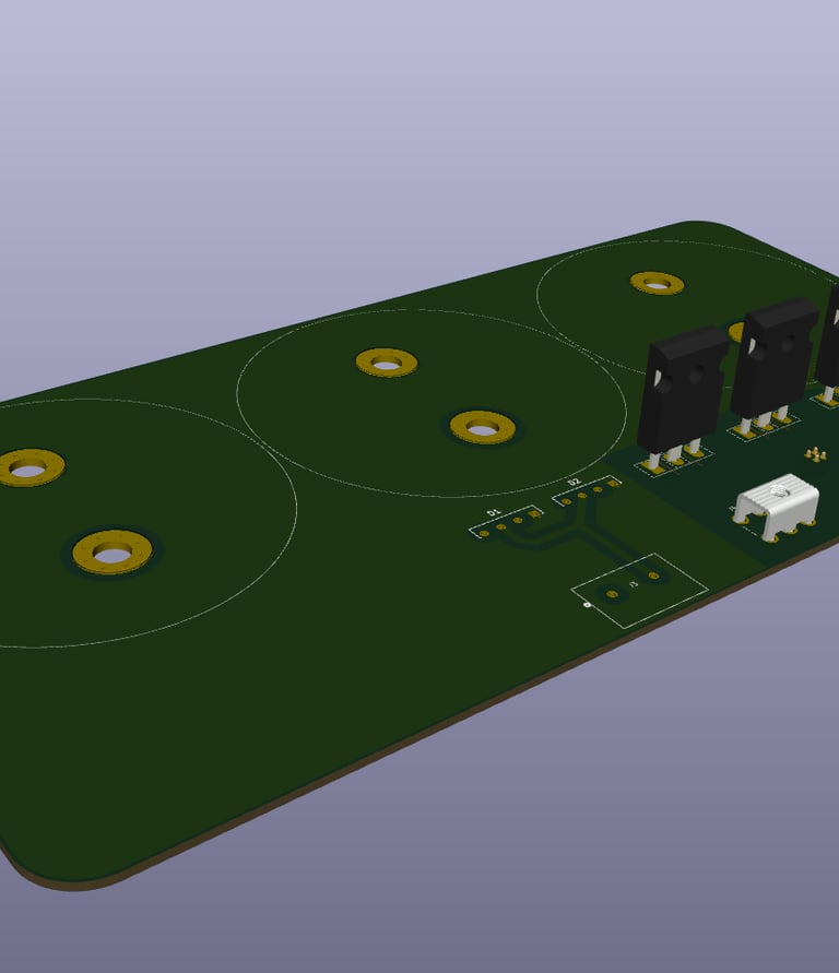
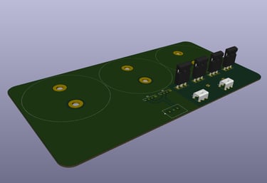
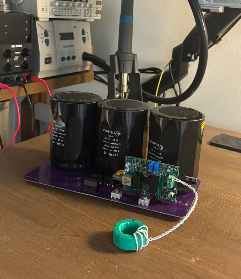
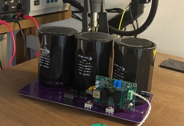
Inverter
3x 2200uf 450v DC bus capacitors. Input from flyback converter for 400v nominal bus. New generation SIC mosfets by ONSEMI. PCB designed in kicad and produced by JLC PCB. Designed for minimal parasitics and adequate high frequency operation. (Left: inverter and mezzanine gate driver Right: PCB for the inverter designed in Kicad)
Resonator
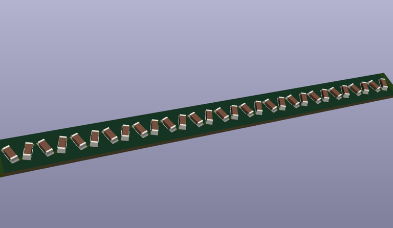
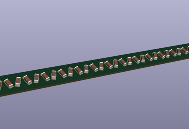
4" by 6" coil form. 28awg magnet wire. Internal Capacitor string made with series mlcc capacitors to low resonant frequency without an excessive top load.


Ramp Generator
I used an Arduino Nano to construct a simple ramp generator to control the gate driver. The Arduino needs to take input from a few potentiometers and generate a pwm ramp signal to send via fiber optic to the gate driver board.
Testing
This project has span over two years and my transition from High School to college
It's Alive
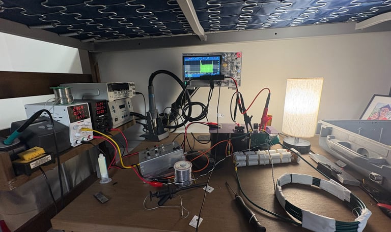
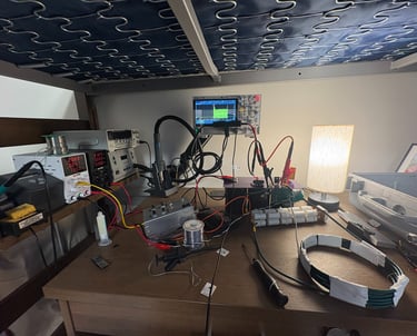
Initial Testing of the Inverter. Using just 30v the inverter shows life. There are harsh switching transients (I have zero snubber capacitors or RC dampers at the moment) and the rf emission is interfering with the hacked together Ramp generator. The inverter is driving a hacked together LC circiut with a resonant frequency of around 375khz. A differential probe and good oscilloscope with good memory depth makes analysis like this easy