QCW Tesla Coil Gun
Using a alternate PWM scheme to achieve straight arc growth in a portable format
Progress
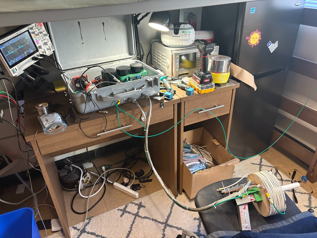
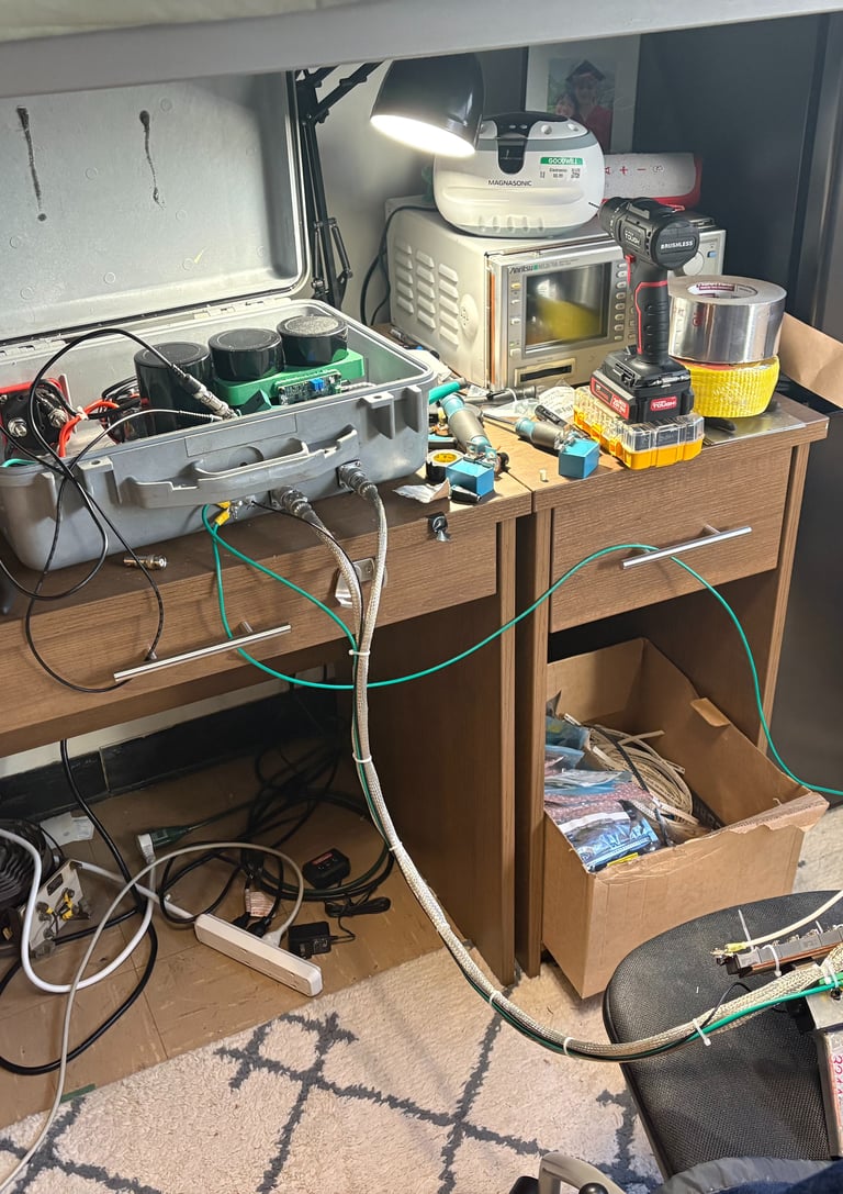
It's Alive
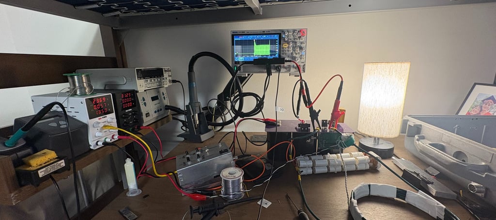
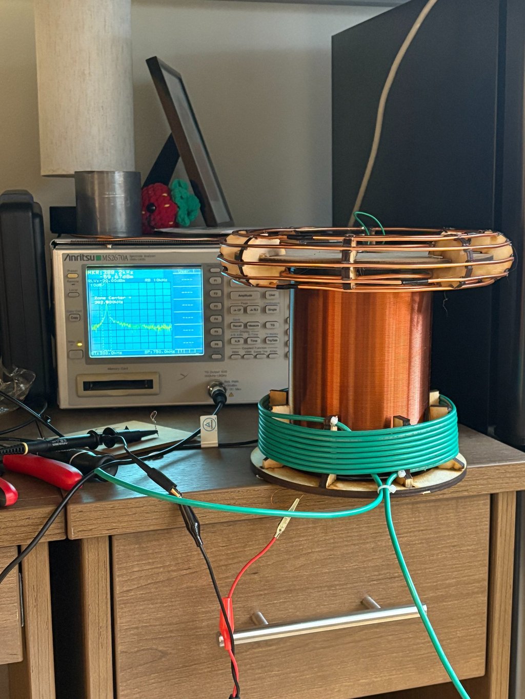
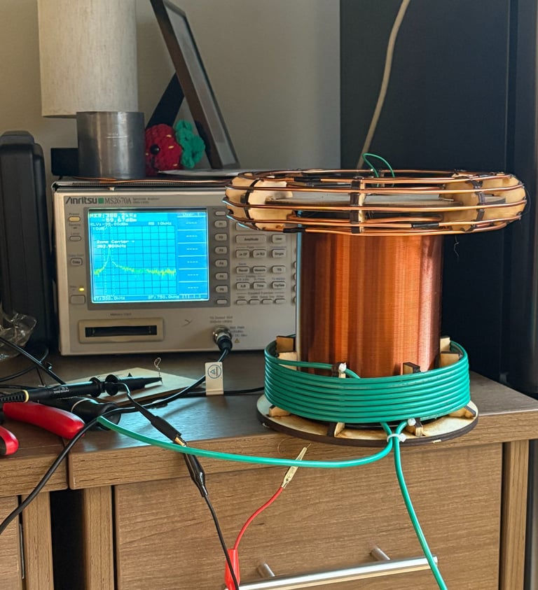
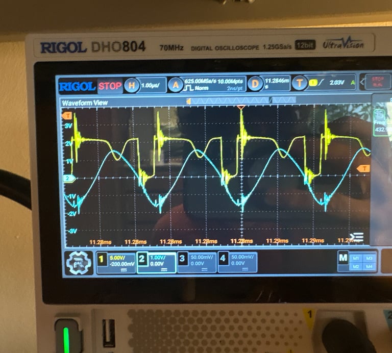
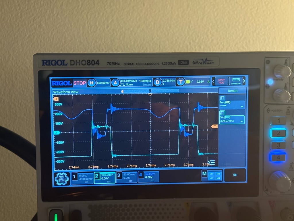
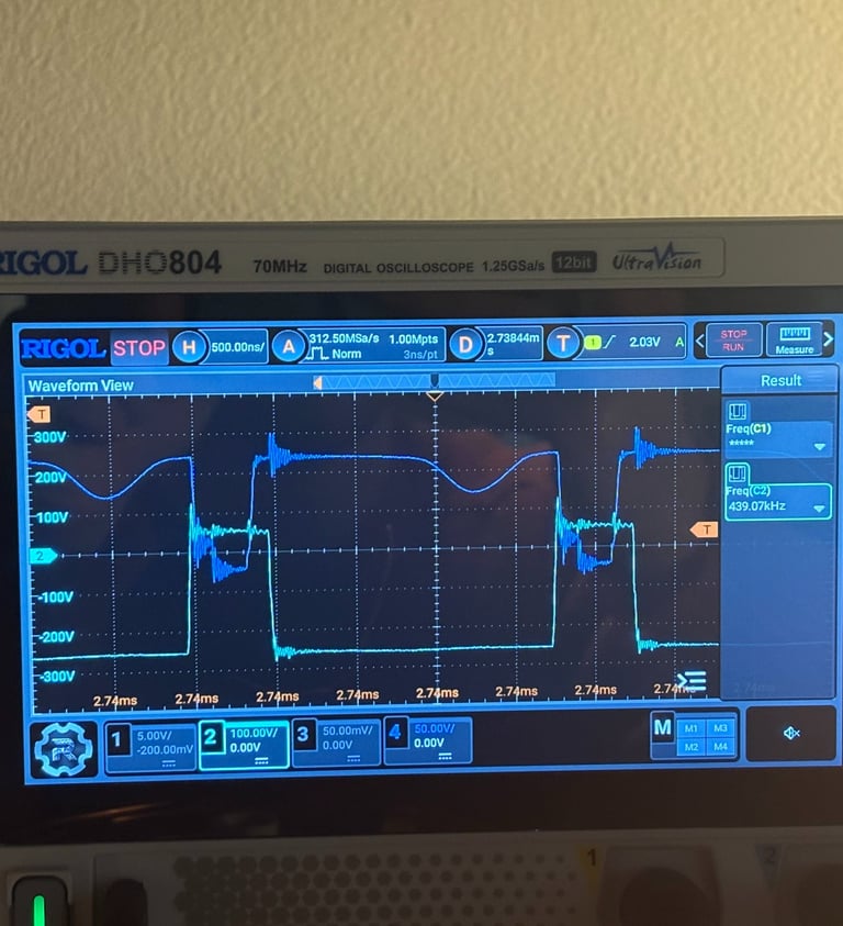
Initial Testing of the Inverter. Using just 30v the inverter shows life. There are harsh switching transients (I have zero snubber capacitors or RC dampers at the moment) and the rf emission is interfering with the hacked together Ramp generator. The inverter is driving a hacked together LC circuit with a resonant frequency of around 375khz. A differential probe and good oscilloscope with good memory depth makes analysis like this easy
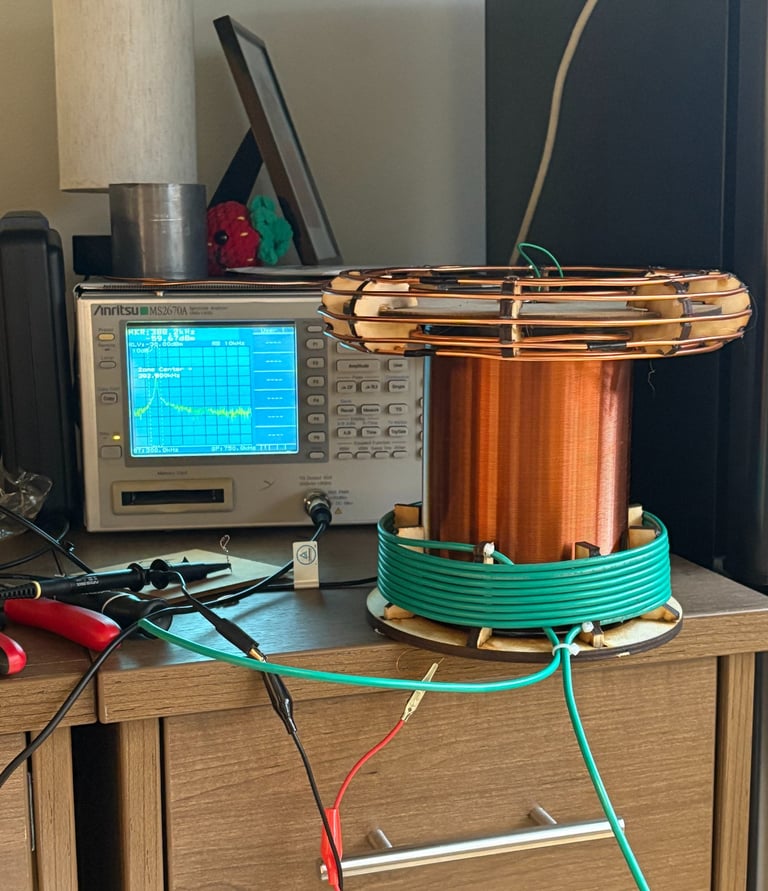
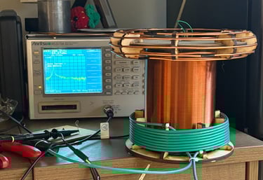
On Tuning and Resonant Frequencies
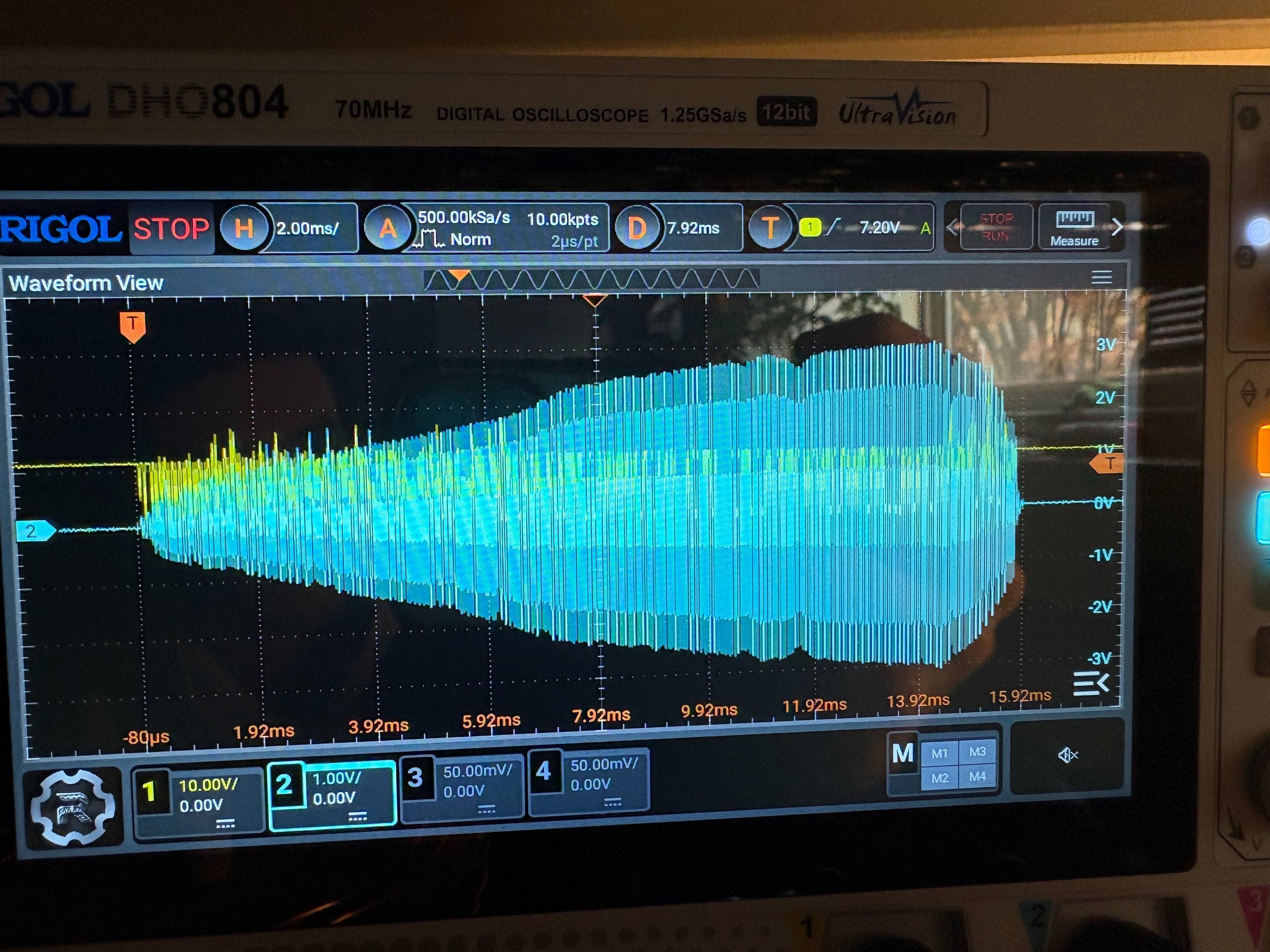
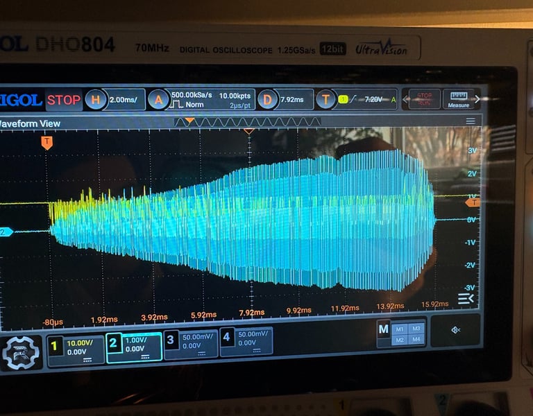
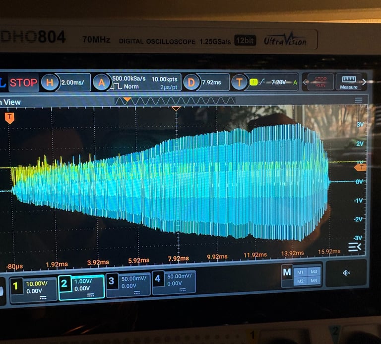
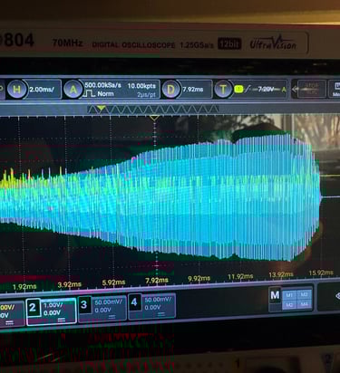
The Primary initially had a resonant frequency of 308Khz, I was happy with this depending on the secondary but after the secondary ended at around 380khz I decided to remove some windings. As mentioned, with the topload and 1 string of the secondary had a resonant frequency of about 340khz which is perfect. I will tune the primary to be around 310-320khz to better match the secondary. Pictured is a nice ramping current envelope (blue trace).
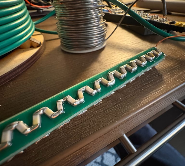
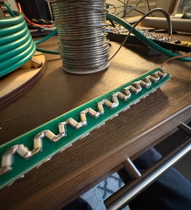
Capacitor String Problems
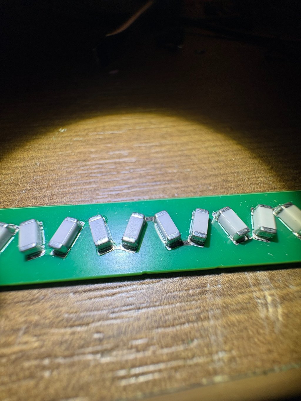
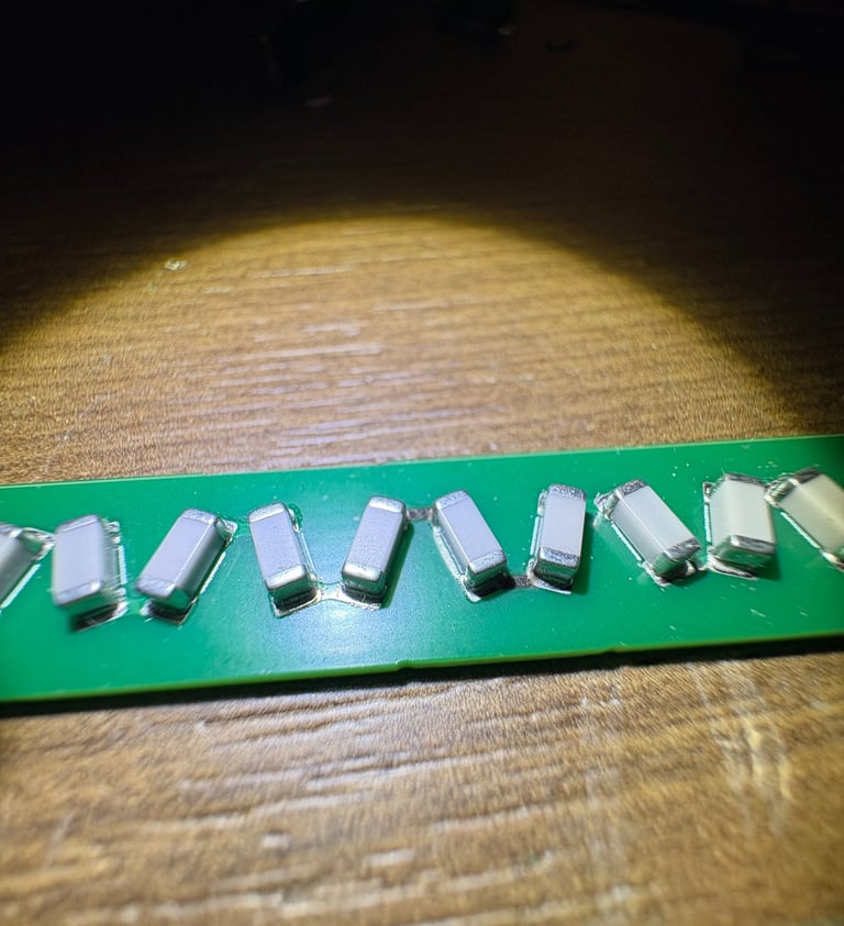
The capacitor strings are nice for tuning and hopefully will be even nicer when I make a more compact secondary coil, but at the moment they are being a pain. I noticed arcing internally and upon inspection the traces on a capacitor string had evaporated. I fixed this with a hefty amount of solder. I am worried about the MLCC's cracking because of a heat, only time will tell.
A Very Hard to Diagnose Inverter Problem
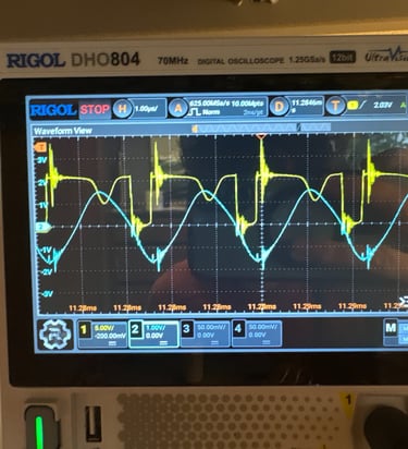
the magnetic field of the output of the inverter was enough to pull the gate of the upper MOSFET low for a fraction of a second whenever the inverter switched on. The actual problem was traced to a PCB trace that I had haphazardly run too close to the RF output of the inverter. Shielding this trace fixed the issue. Left: inverter output. Right: Gate drive signals
Functional Low Voltage Testing

Before leaving for winter break I was able to test it at low voltage!
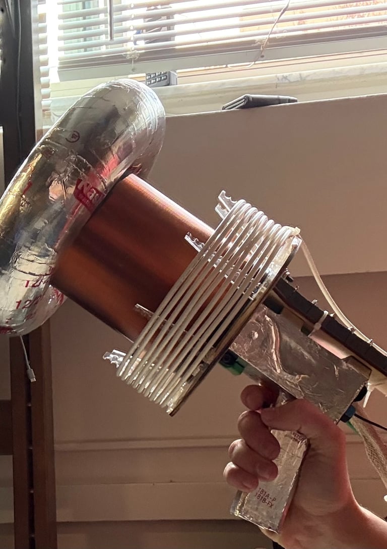
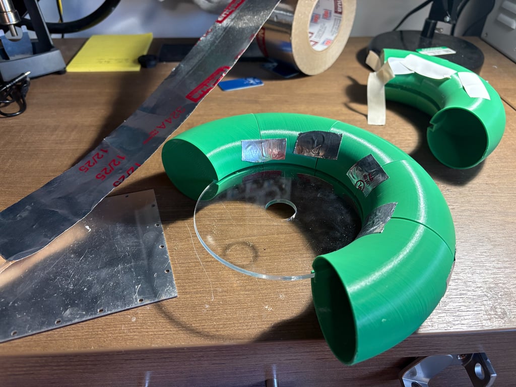
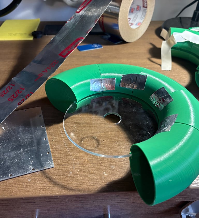
New Topload
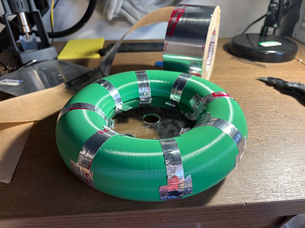
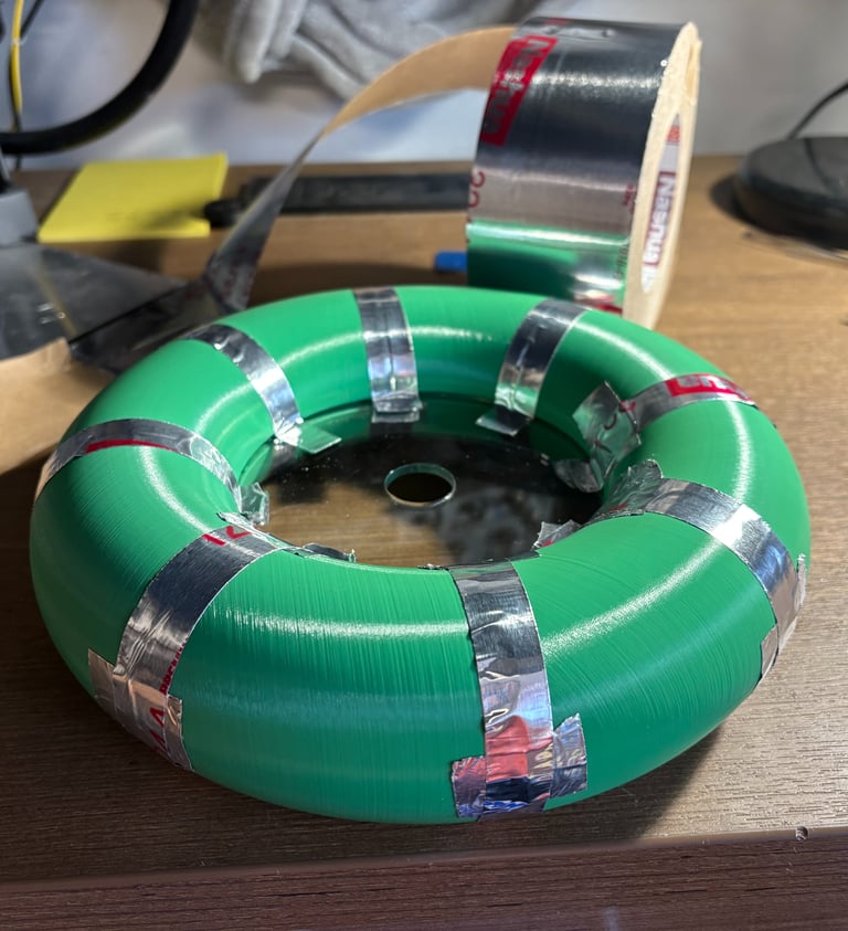
Unfortunately the Top load I have been using had too low of a capacitance, causing the upper pole frequency of the system to reach nearly 500Khz! Obviously something had to be done, so I designed a new one in Fusion 360 and 3d Printed a thin wall Toroid which I coved in aluminum tape. With the new Top load the upper pole is closer to 400Khz, which is still higher than I had hoped for, but maybe after I add more coats of varnish to the secondary it will decrease further.
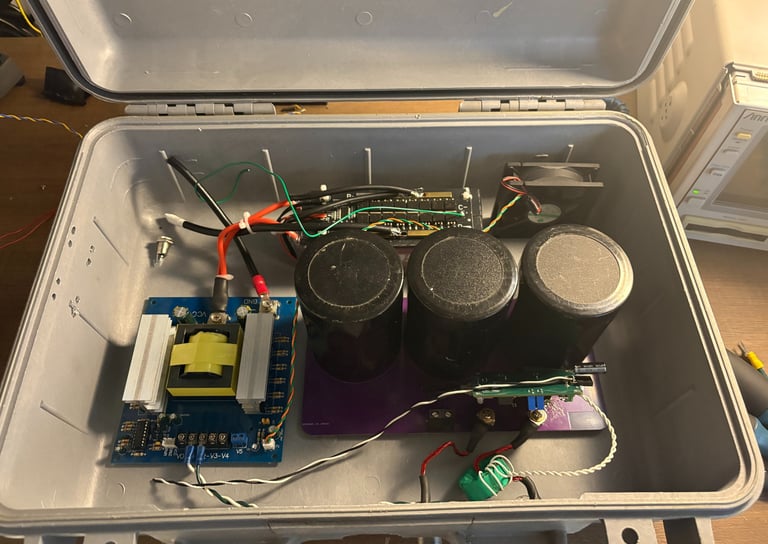
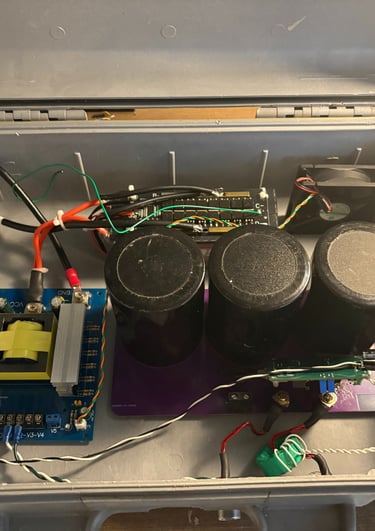
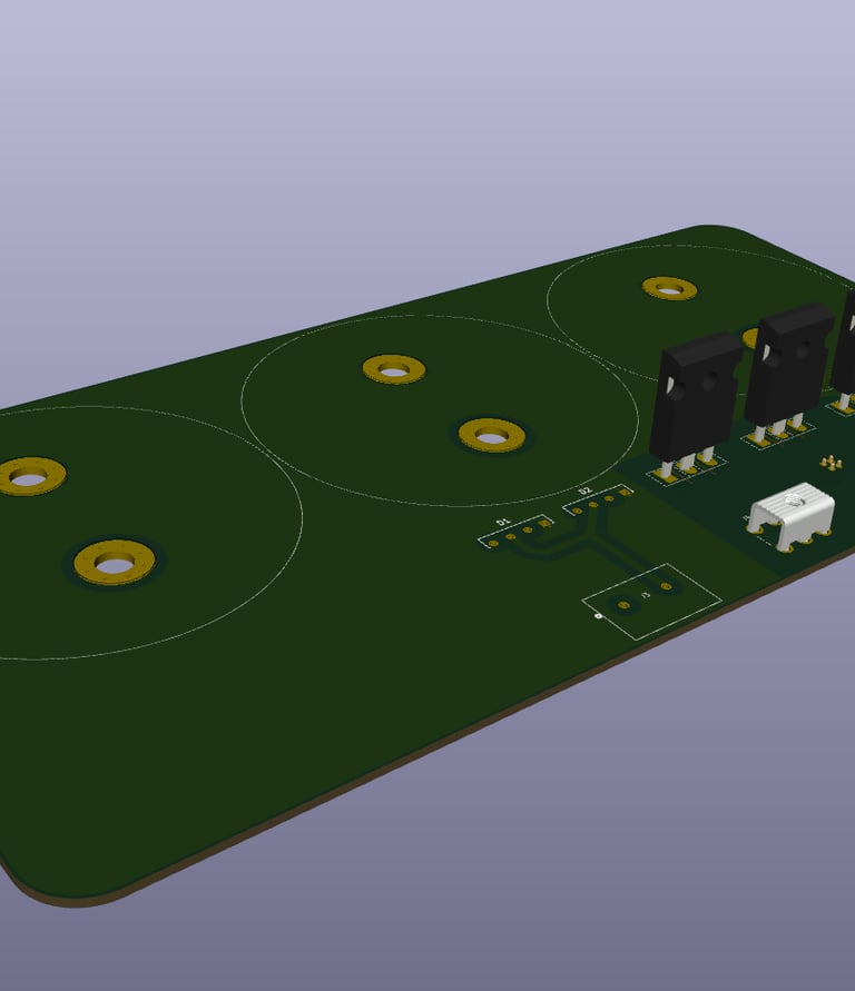
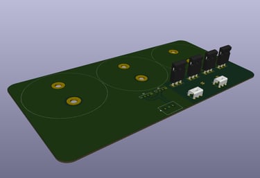
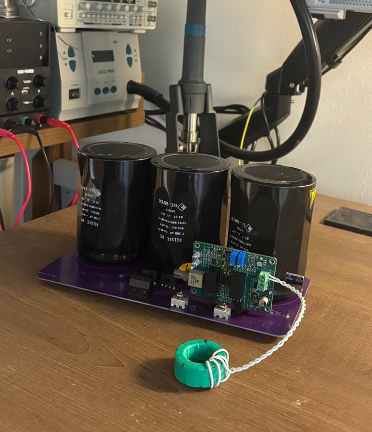
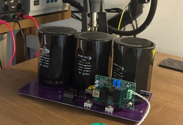
Inverter
3x 2200uf 450v DC bus capacitors. Input from flyback converter for 400v nominal bus. New generation SIC MOSFETs by ONSEMI. PCB designed in kicad and produced by JLC PCB. Designed for minimal parasitics and adequate high frequency operation. (Left: inverter and mezzanine gate driver Right: PCB for the inverter designed in Kicad)
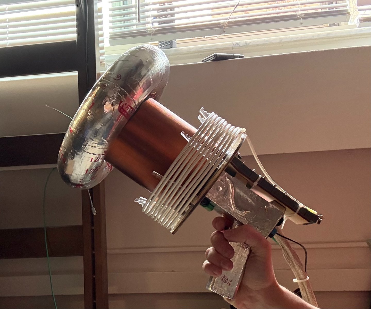
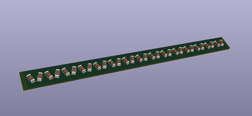
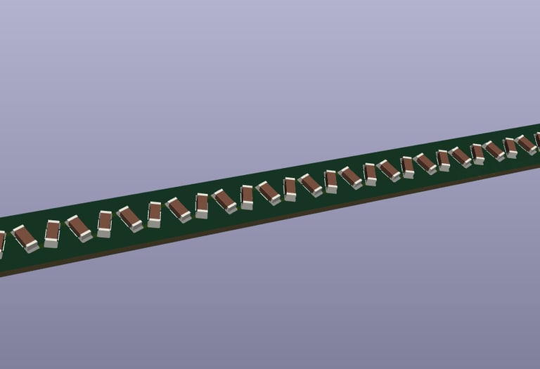
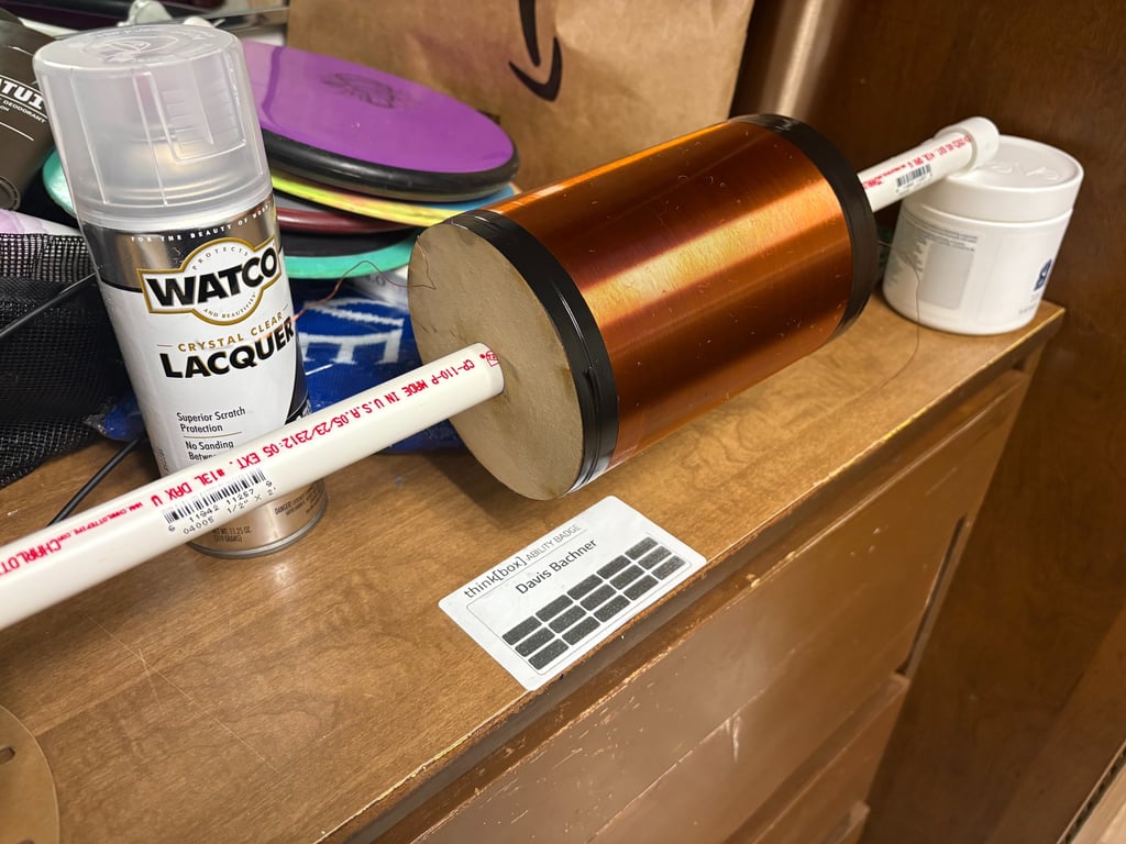
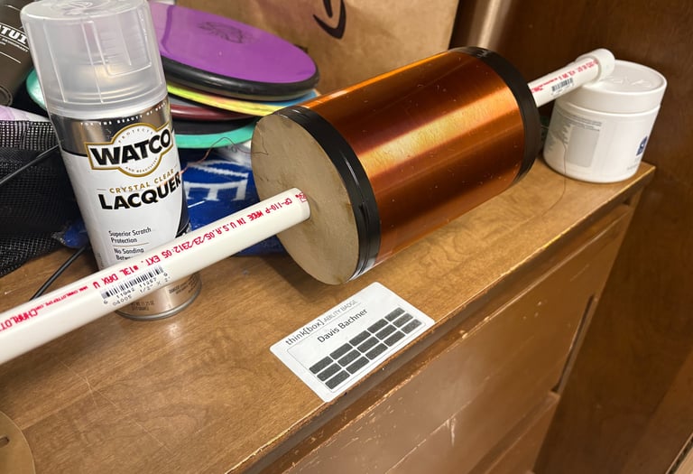
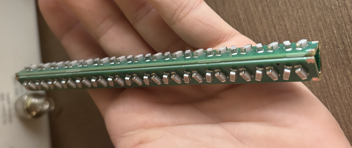
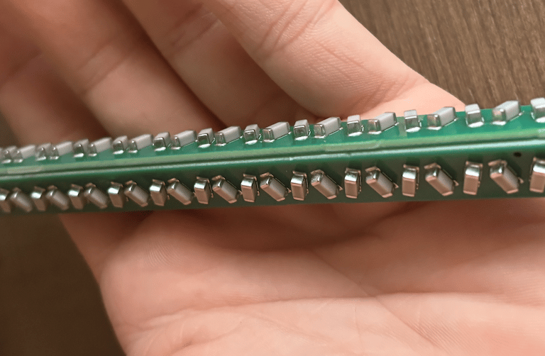
Resonator
4" by 5.5" coil form. 28awg magnet wire. Internal Capacitor string made with series mlcc capacitors each has a capacitance of 10pf, nominal voltage rating of 60kv. Coil was wound and lacquered with a kind of spray on nitrocellulose lacquer, if I were to do it again I would use epoxy.
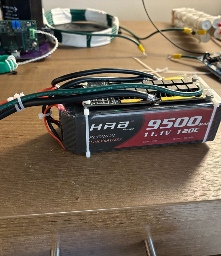
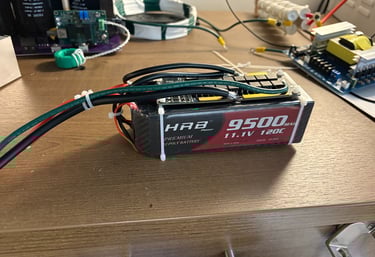
Battery
I'm using two 9600mah 11.1v lipo batteries to power the entire thing. They are directly soldered in parallel to a BMS system and charger. This assembly feds through a breaker and fuse (maybe a relay as well in the future) then is put into an off the self flyback converter to feed the inverter the nominal 400vac it will run at.


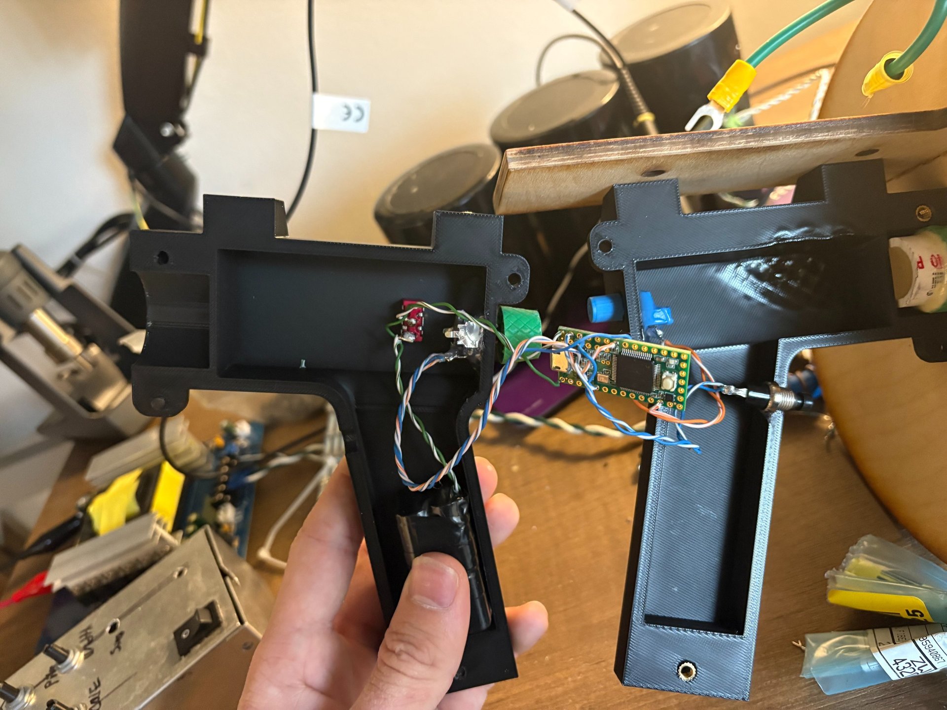
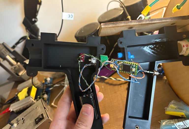
Ramp Generator
I used an Teensy 3.2 to control a simple 'ramp generator'. The ramp generator must create a pwm ramp, around 20ms in duration, to control the inverter board. I designed it all to fit within a cavity in the handle, it uses a button a the trigger and transmits via fiber optic to the inverter board (the signal has to run parallel to the inverter output cables so regular wires would not work). The pulse amplitude is adjustable via a potentiometer. The entire thing runs off of some AAA batteries and is coded in C++.
Combining it All
Things are beginning to work and I have a critical mass completed I will continue to post more photos here. The Hand piece was simple enough once the ramp generator electronics were done. I have continued to improve the code and the entire assembly was shielded with aluminum tape.