TMR Based Current Probe
Using an Tunneling Magnetoresistance sensor to create a DC-5Mhz current

Why?
Current probes are a very useful piece of test equipment. Usually, I would use a current transformer when measuring AC currents, but CTs don't work for DC voltages. The TMR sensors can work with DC into the high frequency range, and a DIY option would make them accessible to the Hobbyist. Professional options cost thousands of dollars, so a low cost alternative would be increadible!
I first became curious about TMR sensors after reading this page on the TDK website: https://product.tdk.com/en/techlibrary/productoverview/tmr-angle-sensors.html There are some clear benefits with these chips over Hall effect or AMR devices, and since I was looking for a new project I thought making a useful device out of these relatively new devices would be a perfect fit!
It Works!
The probe works! After finishing soldering and cleaning the boards I did some preliminary tests and everything seems to work as expected. I was easily able to measure transient pulses by shorting a DC power supply, and DC voltages as well. Eventually I even tested the probe with my AWG and found the bandwidth to be around 5Mhz. I am proud that the flip flop circuit I used for the relay and 1x 10x gain setting it works exactly as expected. I currently do not have access to a high frequency current standard, but when I do I will update the page!


Topology
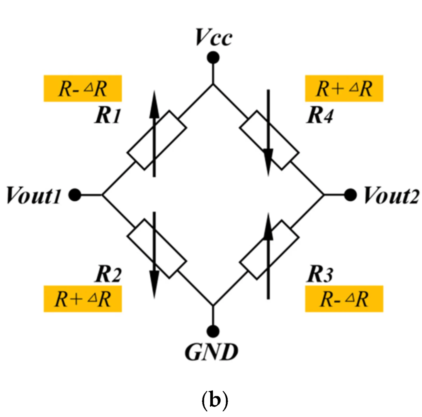
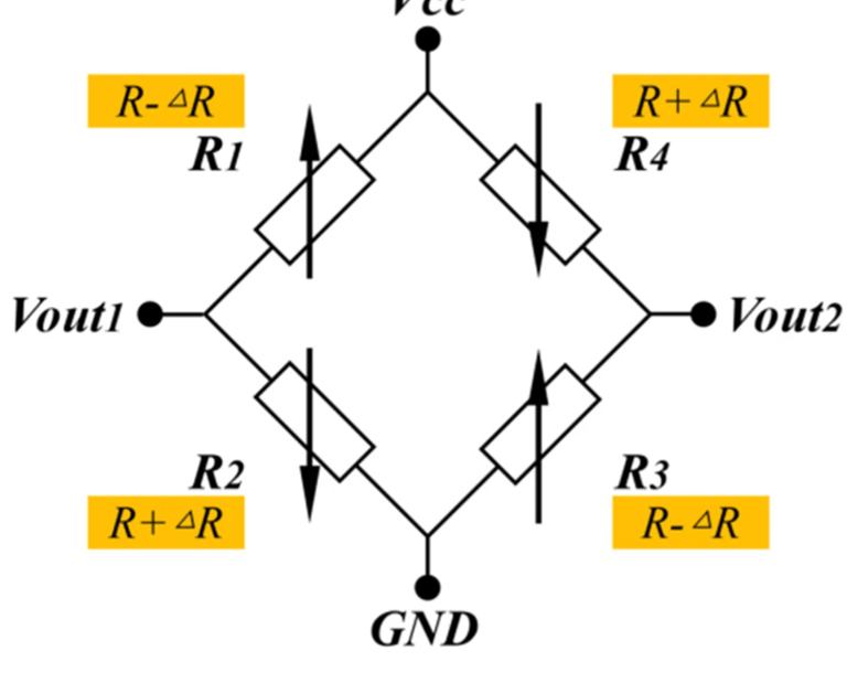
I used TMR based sensors from Multi-Dimension. While they are a company that specializes in this kind of sensor, it is difficult as an American to get them to ship me samples. However, after a long email chain, I succeeded. The chip works by integrating two current sensitive resistors into a classic Wheatstone bridge, outputting a differential signal depending on current fields. I picked the TMR2583 which is their medium spec chip sensitive in the Z-direction. The data sheet is a little sparse but from some research I was able to create a circuit that works with these chips.
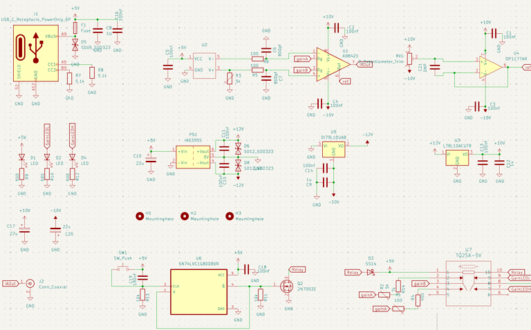
Schematic
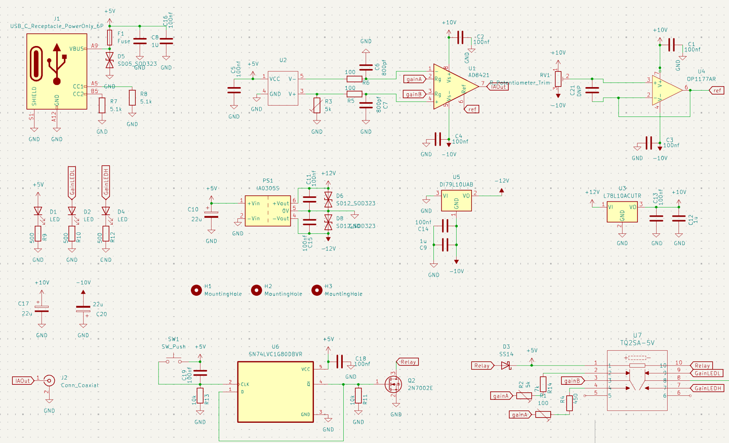
The circuit uses a simple instrumentation amplifier circuit using the AD8421. Something of note is the isolated dc to dc converter I used to get my 12v rails. These isolated, dual output devices, are very convienent for split power rails used by many op-amp circuits. unfortunately, due to tariffs and shifting industry needs they are becoming expensive and hard to find. The circuit I use to control the relay is a D type flip flop that acts as a latching circuit for a push button. The relay controls the gain of the IA for hopefully 10x and 1x modes in practice. For revision 2 I would like to add a microcontroller for auto zero and to simplify my design.
Circuit and PCB Design
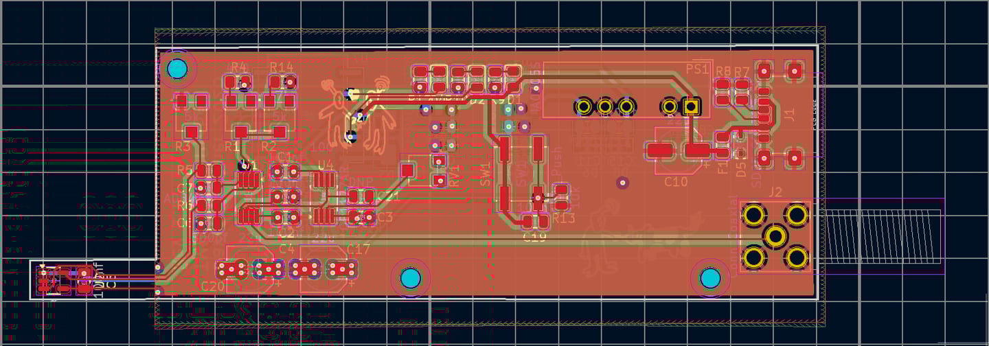
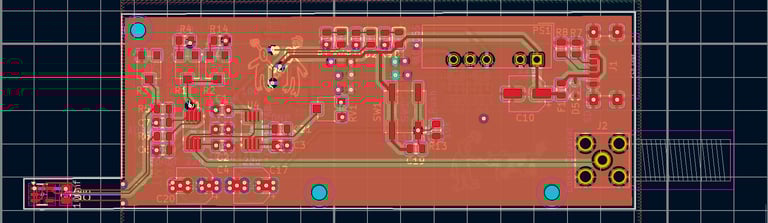
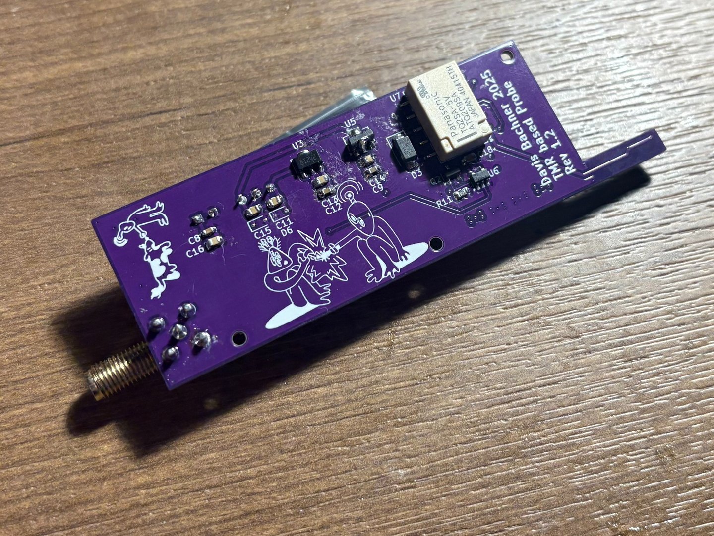
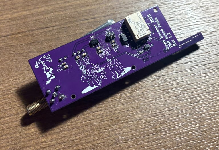
I created a quick 4 layer board design using KiCad. I chose four layers so I could keep the layout clean and compact. The boards were ordered on JLCPCB and populated by hand using a regular iron and hot air. The KiCad to JLC to home pipeline really does make these projects a breeze.
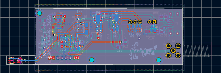
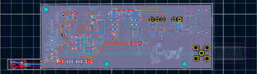
PCB
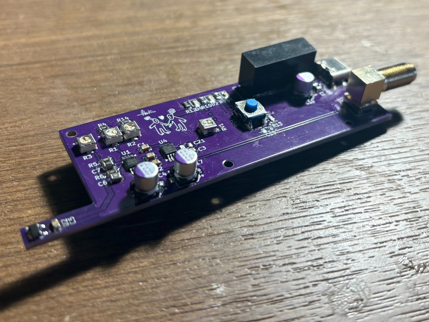
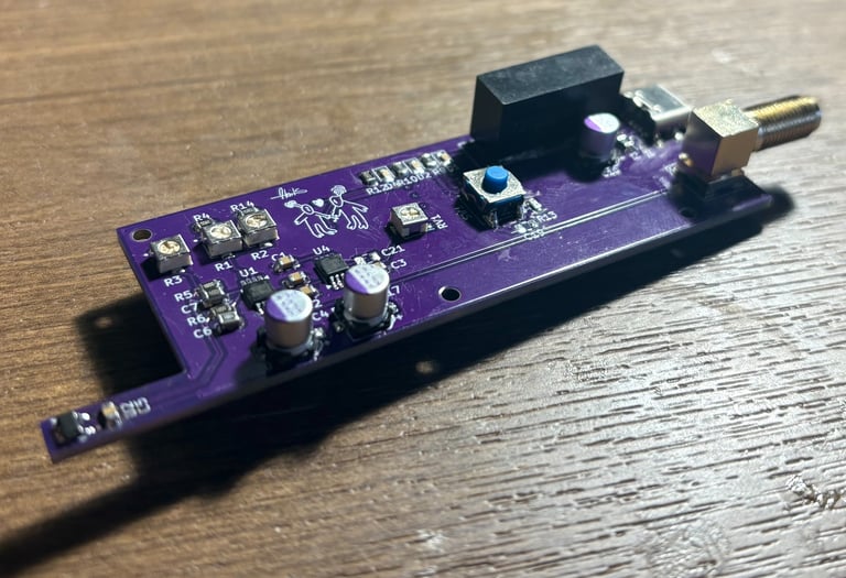
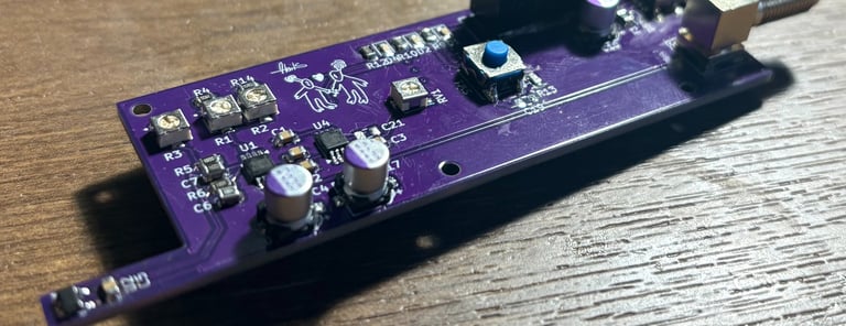
Boards Arrive
The boards arrived from JLC PCB and were cleaned, populated, then cleaned again. I made two small footprint errors, flipping one of the regulator pinouts and picking the wrong package size for the dc to dc converter. Both ended up being fixable issues; the regualtor was mounted upright and the dc to dc converter was soldering floating a few mm above the rest of the board.