Capacitive Morse Code Keyer
Using a simple capacitor touch sensor IC (AT42QT1011) for CW paddles.
Why?
I recently got my HAM radio Technician License and am taking the test for my General License soon. I am new to HAM radio as a hobby and morse code, or CW, seems like a good intro to communicating with others on the frequencies. I was looking at CW paddles online (the thing you use to great the dots and dashes) and I thought it wouldn't be to hard to throw together a capacitive touch sensor myself to beginning learning this new language.
Topology
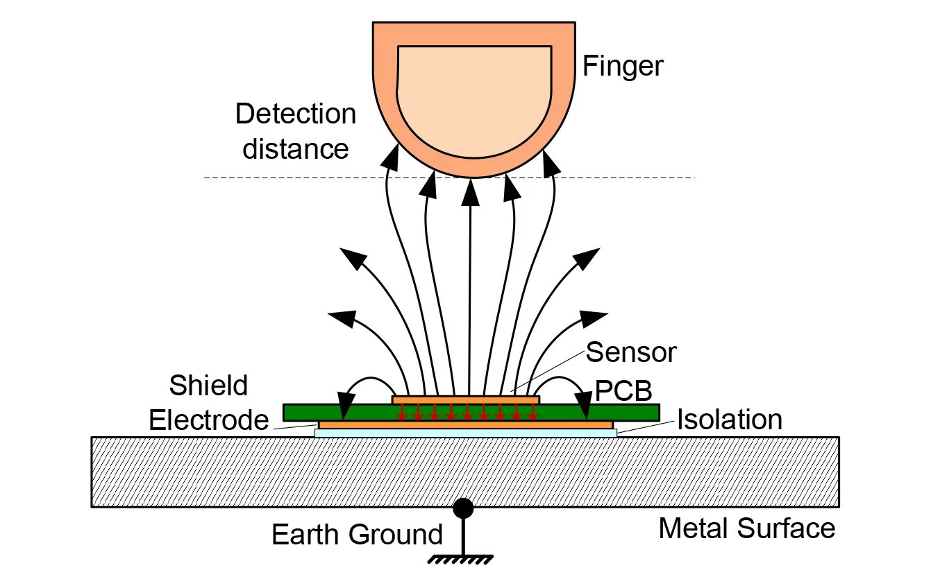
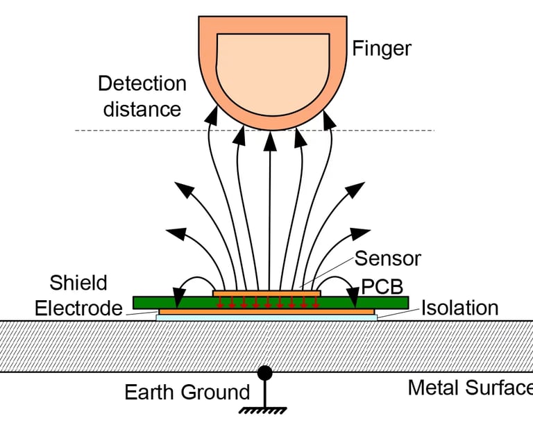
I used the AT42QT1011 chip which is something microchip calls a, "digital burst mode charge-transfer" chip. It uses the changing charge of an electrode upon capacitive loading by a finger or some other grounded conductive object to detect motion and touch. It is useful for me because when it detects a touch on an electrode it sets its output high, which can be read with a microcontroller. I plan on having two of these side by side, one for dots and one for dashes, with an Arduino or teensy to monitor the chips and output a key signal to my radio.
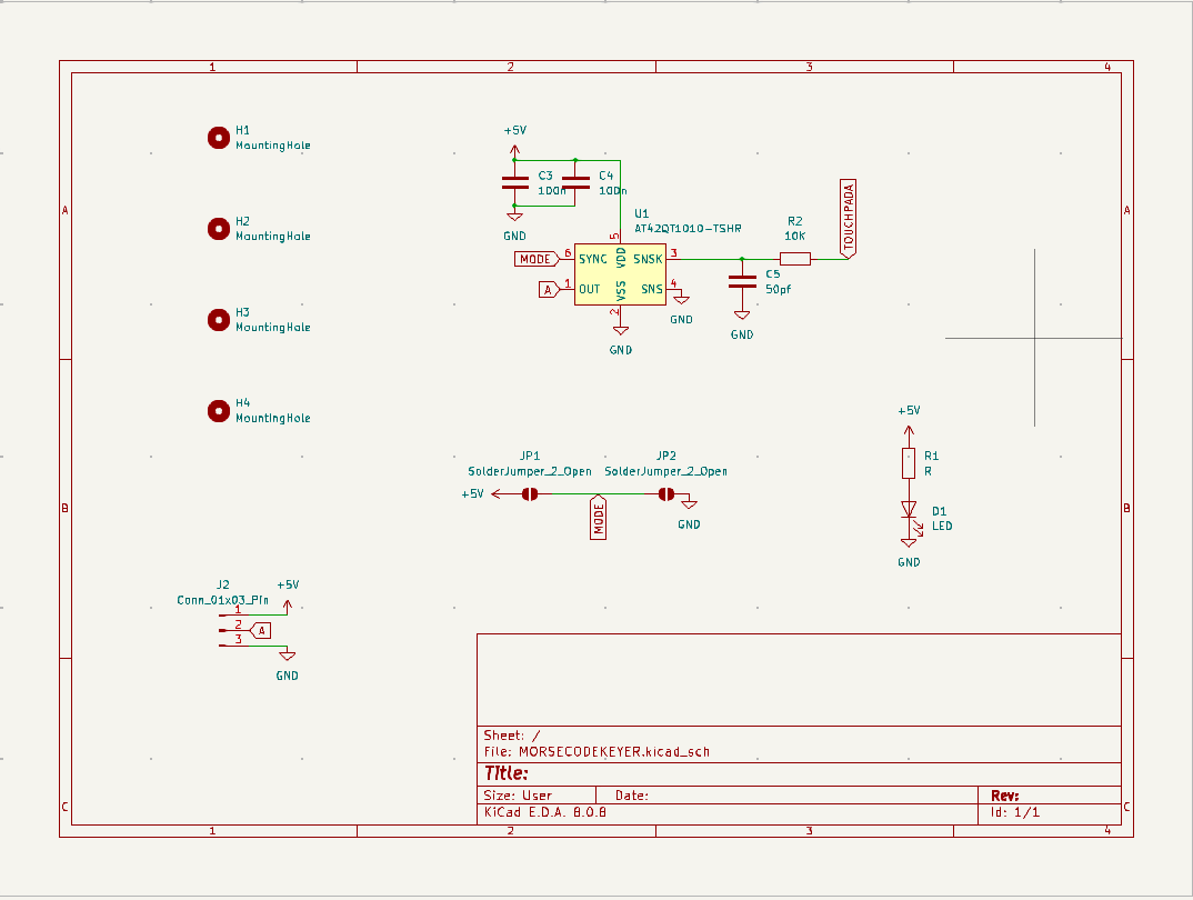
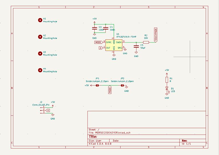
Schematic
The schematic for the touch board itself is actually very simple for this project! only a connector for the Arduino, a few decoupling capacitors, the touch IC itself, an LED, and some mounting holes. More fun comes in the PCB design below, some things to note in this schematic: The TOUCHPADA net label is attached to the electrode on the PCB which is not given a symbol on the schematic because it is simply a copper pour. The jumpers select the "Mode" of the IC, they are simple solder jumpers, one to connect the mode pin to high which puts the chip in "fast" mode and one to connect the mode pin to low which puts the chip into "slow" mode. Fast mode allows the IC to change its digital output state more frequently, I do not currently know morse code so I did not know which to pick, hence the jumper selection.
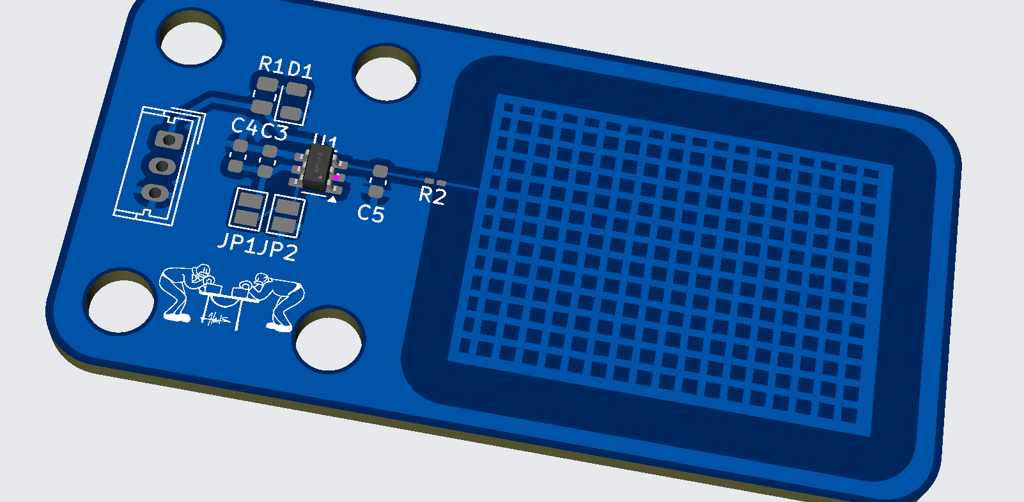
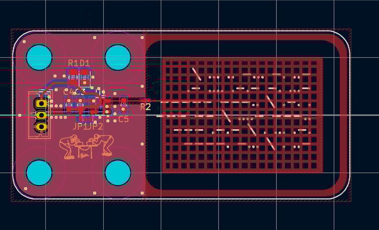
Circuit and PCB Design
The exciting part of this PCB and project is the capacitive electrode, which is the mesh on the right of the board. The electrode poses some interesting design considerations. I left a ring of ground pour around the electrode to stop its electrical field from propagating vertically. Initially I had planned to use two IC's and Two electrodes on one board to make construction easier, but having ground planes near the sensor ( I would need to place one between the two electrodes in the case of a dual sensor) seems to have some unattractive drawbacks in sensitivity. After reading the microchip paper on designing electrodes it seems that field testing and tuning the loading capacitor is the way to make these sensors behave as expected.
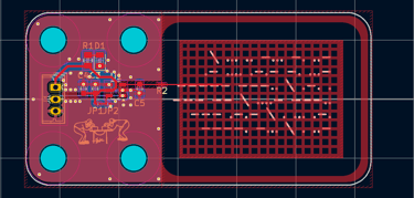
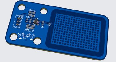
PCB
More Coming...
The PCB's have been ordered from JLCPCB with the touch IC pre-assembled to save me the extra shipping charge. I am currently designing a base for the paddles and writing code for the microcontroller. (I am also learning morse code to test these, we will see if I can learn it quicker than I can build this)