QCW Tesla Coil Gun
Using a alternate PWM scheme to achieve straight arc growth in a portable format
Why?
Tesla coils fascinate me because they combine so many electronics disciplines and also physical construction challenges. From RF to power electronics this project certainly covers a wide range of disciplines.
I started this project at the end of High school as a personal capstone project. While I am sure there is no functional use for a tesla coil backpack I have learned so much while undertaking this project, and to me it has been worth it.
I will not be going into depth on the basics of tesla coils, their design, or their operation. I do use some terms that may be confusing, so I recommend reading this page be Loneoceans: https://www.loneoceans.com/labs/qcw/
Process Photos
I took lots of photos while this project was under development, I have attached a few of my favorites below
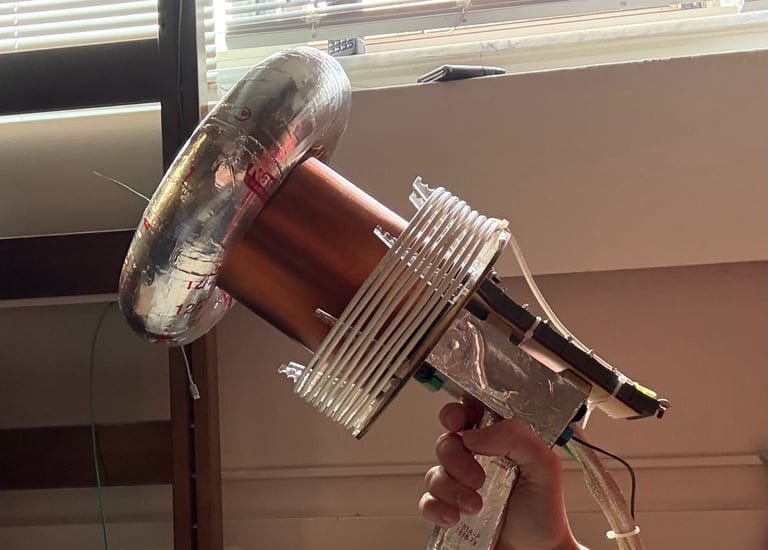
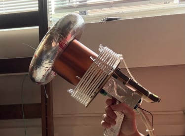
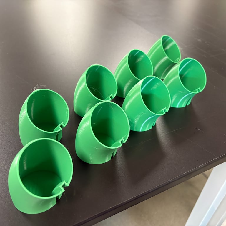
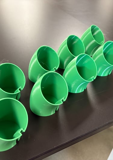
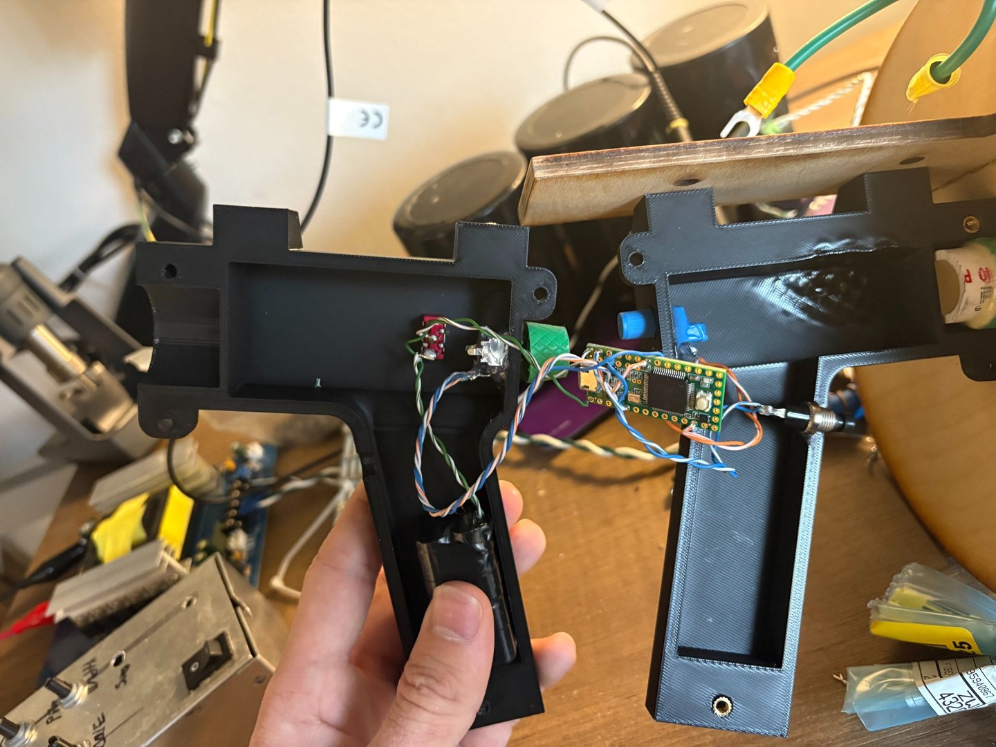
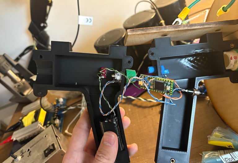
The finished Hand Piece
After 3 different revisions I landed on this combo of laser cut and 3d printed pieces. The handle contains the control electronics and with careful grounding I tried to make this project as safe as possible.
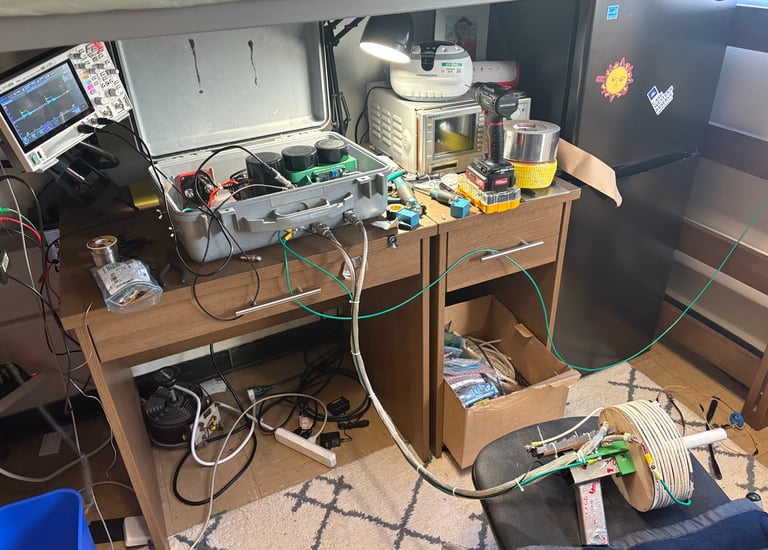
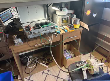
The State of the Lab
Towards the end of the project the "lab" underneath the bed in my dorm got a little out of hand. Testing was not easy in the space because the project required so many tools and components to be on my small desk at once.
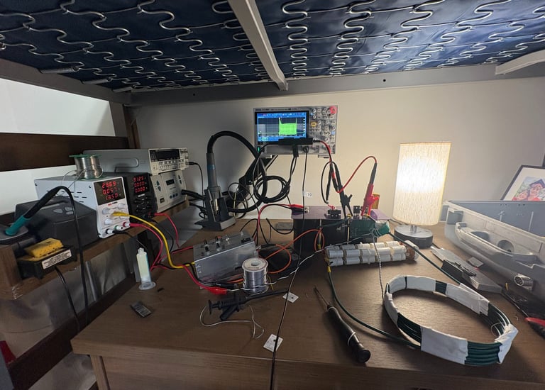
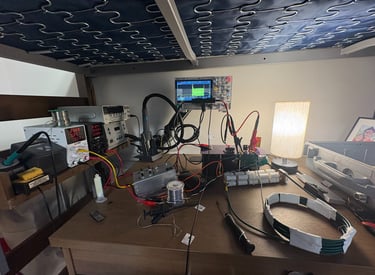
Early Testing
Before anything even got put into the pelican case there was lots of troubleshooting to do. I like this photo because at this point it felt impossible that it would ever be finished but of course I just needed to push on.
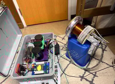
Taking Form
At this point the project began to look like what I had been imagining in my head for so long. Even though the project was 80% done the last 20% was the hardest part! There was so much to do after this point.
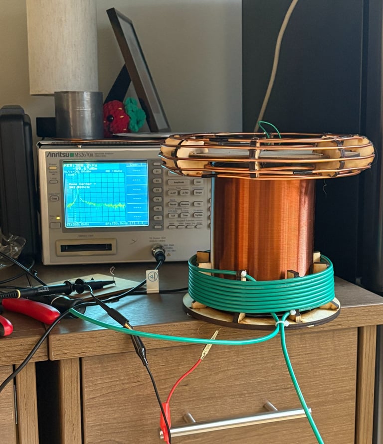
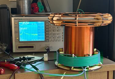
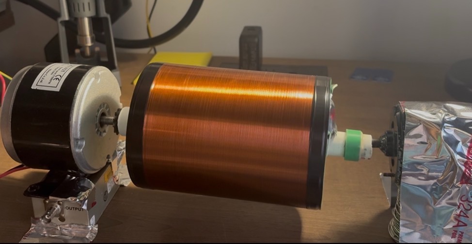
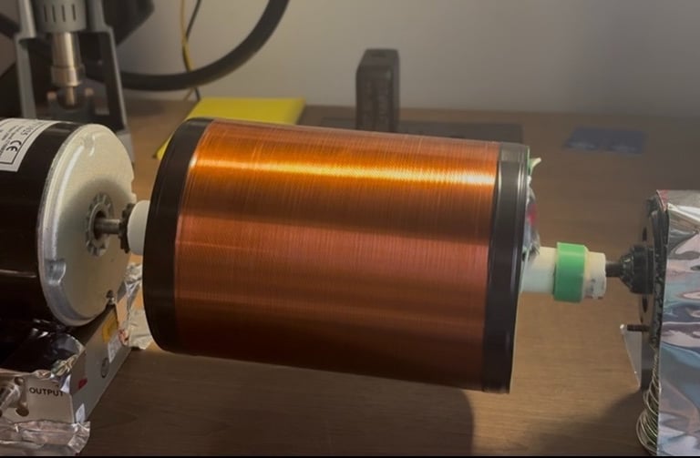
Resonator
I wound the resonator coil on some Home Depot 4" PVC pipe using 28awg magnet wire. My goal was to have the coil resonate at 320khz but I was about 10% high. I originally planned on using a string of MLCC capacitors inside of the secondary to keep the resonant frequency low, but decided to use a larger top load instead. I used a stack of ferrite cores inside coil to increase coupling.
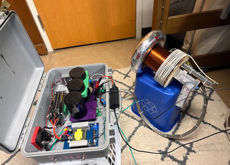
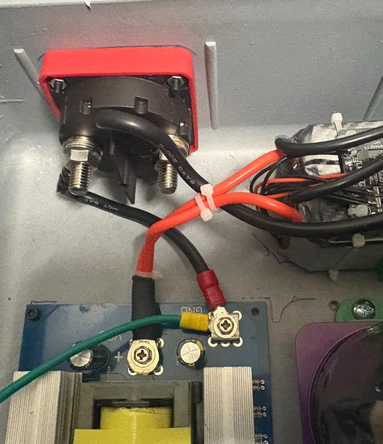
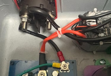
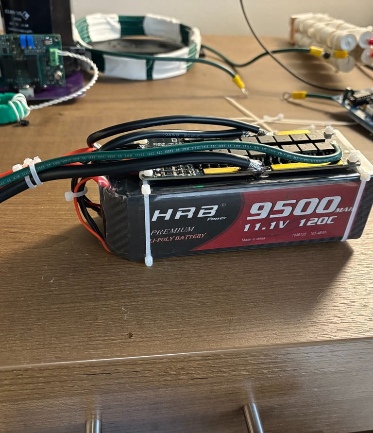
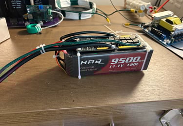
Battery
I'm using two 9600mah 11.1v lipo batteries to power the coil. They are directly soldered in parallel to a BMS system and charger which needs to be bypassed during operation due to the 40a current limit on the bms. The battery is interrutepted by a switch and fuse and then is boosted by a flyback converter to 420vdc. The coil would be more efficient at higher voltages but the capacitors and flyback converter I am using can't handle a much higher voltage. These batteries have had plenty of capacity for testing, I will be curious to see how they do when I increase the power!
Ramp Generator
I used an Teensy 3.2 coded in C++ for a simple ramp generator. The ramp generator creates a pwm signal which is sent over fiber optics to the control board mounted on top of the inverter. The handle runs off of a 9v battery which gives me a few hours of runtime, the signal is adjustable via a potentiometer and has a push button trigger. The electronics inside are not complicated since the teensy does most of the heavy lifting, just a voltage regulator and some indicator lights. I designed it all to fit within a 3d printed handle since I wanted the user to have easy access to the settings.
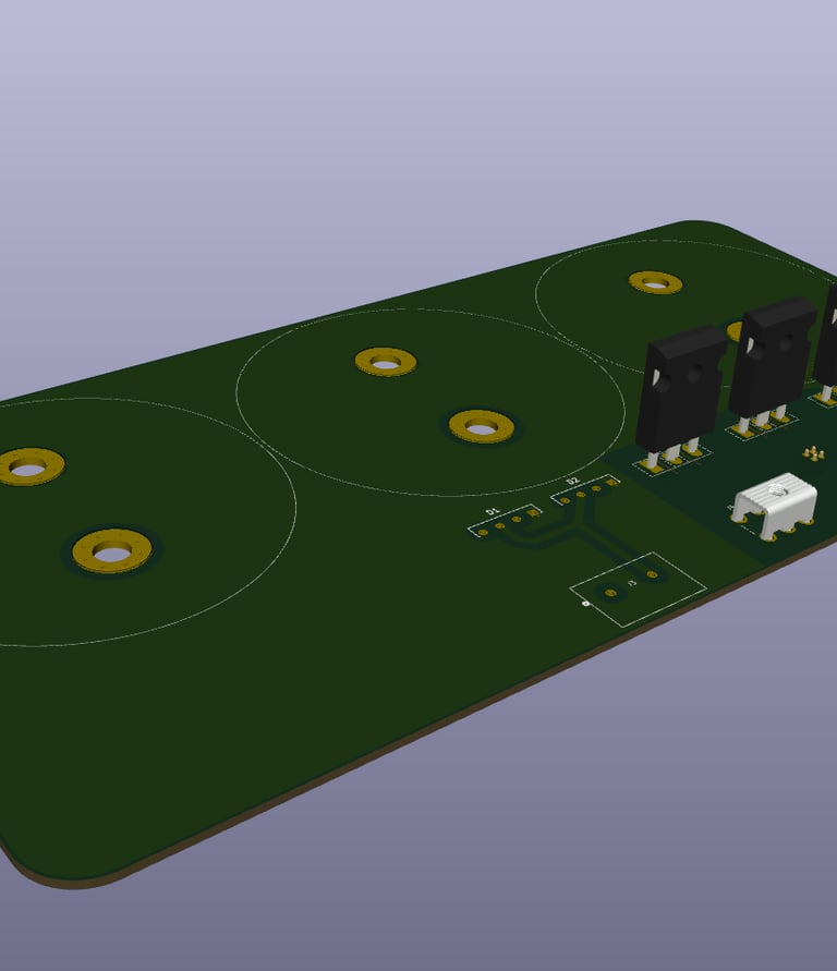
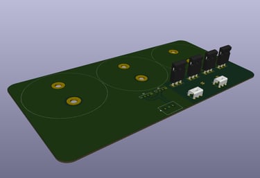
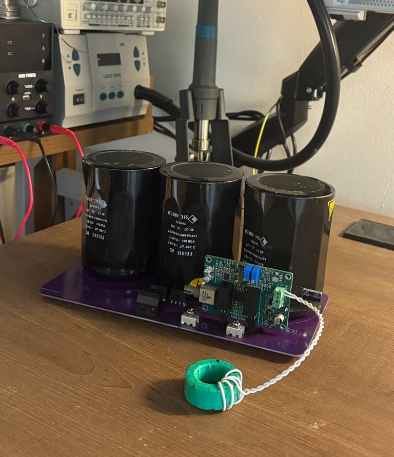
Inverter
I am excited for this inverter because I got to use new generation SIC MOSFETs by ONSEMI. SIC has a ton of advantages for a tesla coil, mainly very fast and efficient switching with a higher voltage rating as well. Since the coil is battery power most of the energy of each spark is pulled from the DC bus capacitors. I used 3 2200uf 450v DC bus capacitors to ensure I had plenty of overhead. I designed a PCB in KiCad with minimal parasitics, I think it came out quite nicely. I had issues (noted in the troubleshooting section) with some gate traces running too close to the inverter output, but after some careful Dremel work the inverter works great! I learned a lot designing and testing it, I am sure I can do much better next time around.
Trouble Shooting
And lots of it
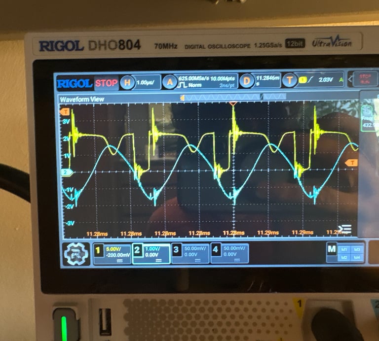
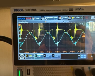
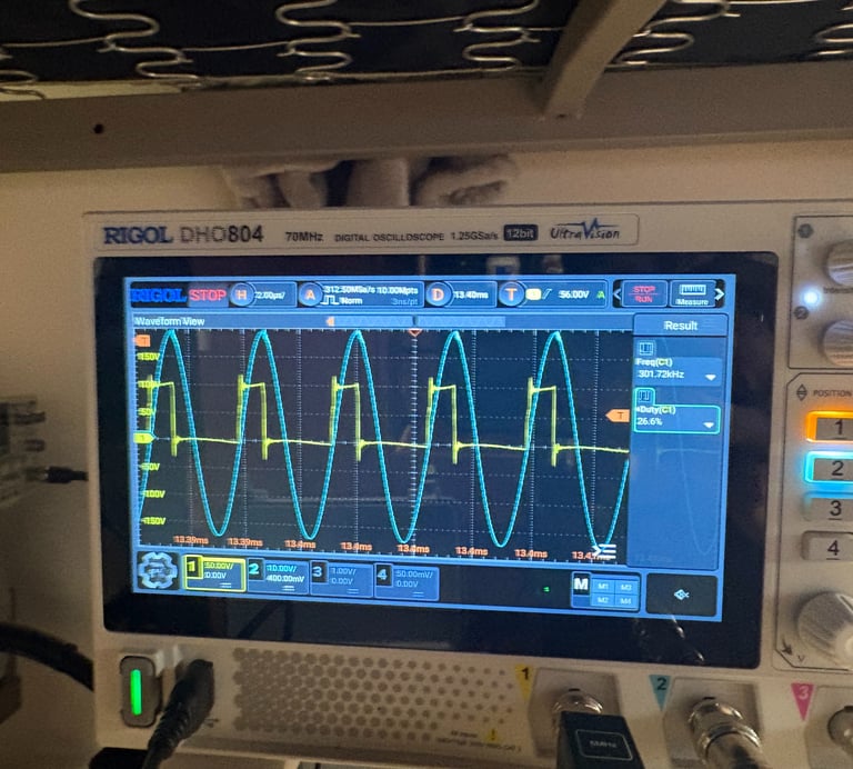
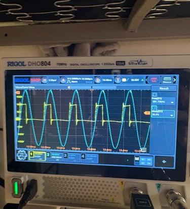
Current Inducing Fet Turn off
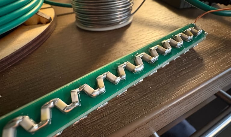
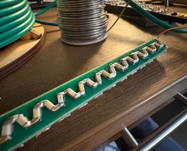
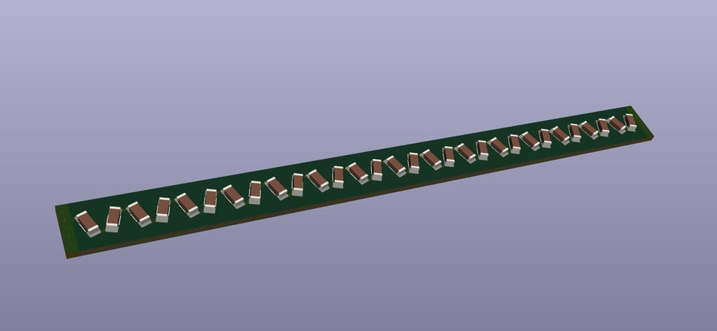
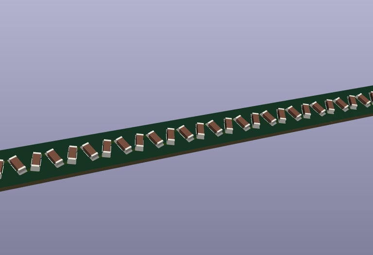
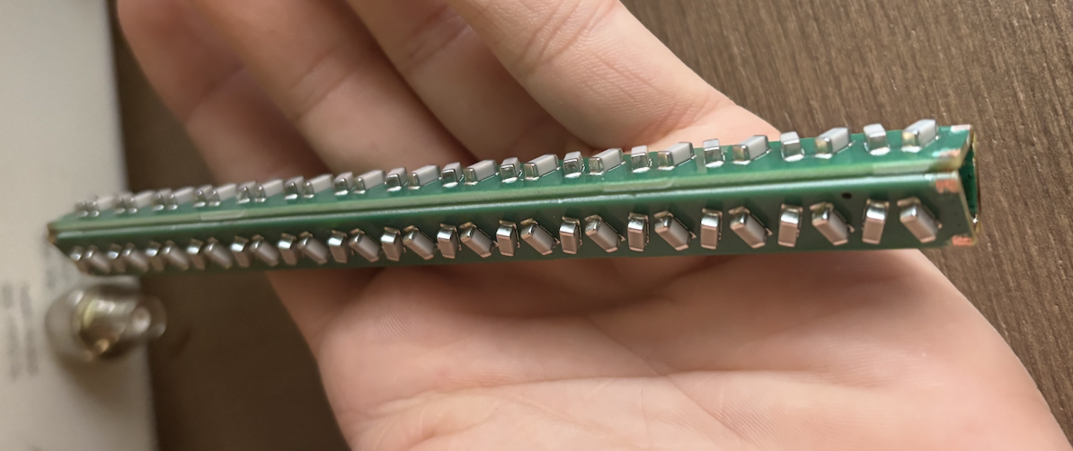
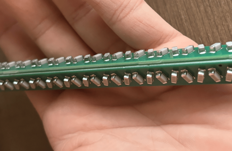
Capacitor String Problems
I intially decide to use strings of MLCC capacitors to lower the resonant frequency of the secondary coil. However, I had so many capacitor strings issues that eventually I decided that to scrap the idea all together. The first issue was every few pulses a trace on the capacitor string board would explode, the capacitance would drop, and the resonant frequency would shoot up. The other issues was standoff distance. I do not thI think I designed these board to withstand a high enough voltage. I designed them to a minimum spec of 70kv, but 100-120kv would have been safer. While capacitors could be used effectively, my implementation was a failure.
This problem was almost the end of me. The EM of the output of the inverter was enough to turn off the upper MOSFET for a millisecond. The problem; a PCB trace haphazardly run too close to the RF output of the inverter. Shielding this trace fixed the issue, but it took hours to discover what the issue actually was beacuse I would test with very low currents. The output looked fine at these low powers, the issue only showed up when I disconnected my equipment for high power testing. Initial problem waveform on the left, and a very crisp output on the right.
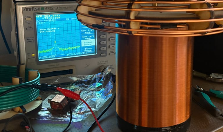
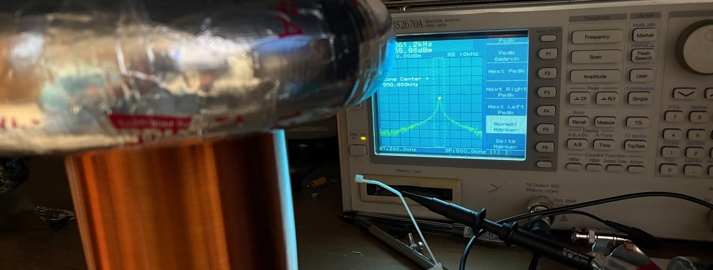
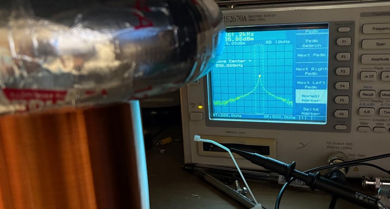
As discussed above I planned to use capacitor strings to tune my secondary coil. However, due to my last minute change from an internal capacitor to an internal ferrite core the resonant frequency of my secondary with my original topload ended up around 490Khz. I ended up 3d printing a new topload and raising it about an inch above the secondary coil so the bottom of the torus was level with the top of the windings. This left me with a coil that had a resonant freq around 370Khz, with the added benefit that my new top load was much more robust.
Adjusting the resonant frequency
Finished Product (coming soon)
While the cool is not yet done click the video link below for low power testing